Ceramic filters as industry knows them best are often called “candles” because of their solid tube shape. They have been a staple of air pollution control for decades. The original ceramic filters were manufactured from refractory grains such as alumina and pressed into the basic candle shape – a tube with a closed, rounded bottom and a flange at the top.
The high temperature filters used in the UltraCat are very different in their design, service life, and multi-pollutant functionality. They are also robust and self-supporting without any filter cages. Tri-Mer filters control SO2, HCl, NOx and particulate (PM) in a single very efficient system and can be adapted to handle mercury and dioxins as well.
How they work:
The high temperature filters start as a slurry of refractory fibers and are vacuum formed into shape. They are very lightweight, approximately 90% open with much lower pressure drop.
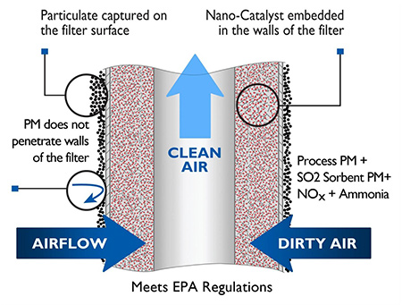
Catalytic Cermaic Filter / Clean Air Diagram
 Air Filtration Diagram
| Pollutants Removed |
Tempature Range |
| Particulate matter (PM) |
300°F to 1650°F |
| PM + SO2, HCI or other gasses |
300°F to 1500°F |
| PM + NOx |
300°F to 750°F |
| PM + NOx + SO2, NCI & other acid gases |
450°F to 750°F |
In the ceramic catalyst filters, the catalyst particles are micro-porous, and due to their small size, they catalyze the gas phase reactions without diffusion and restriction (i.e. almost 100% utilization of the catalyst intrinsic activity) as opposed to usual pellet or monolithic catalysts. In industrial plants, the conventional catalyst types typically operate with 5-15% catalyst effectiveness in the SCR (Selective Catalytic Reduction of NOx by NH3).
High temperature filters must operate above the condensation temperature of water vapor. Liquid water does not damage the filters but inhibits operation. The chart below shows typical operating temperatures for the ceramic filters.
The ability to operate up to 1650°F offers unique opportunities for the removal of PM and other pollutants prior to a heat recovery device, reducing operational issues associated with plugging and fouling, unlike a normal fabric filter.
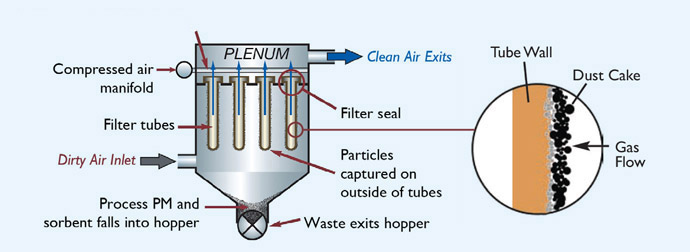
Standard reverse pulse jet methods, commonly used in fabric filter baghouses, are used for filter cleaning. A pulse of compressed air is sent down the center of the filter tubes and cleans the accumulated air emissions from the outer surface of the tubes. The particulate falls into a lower bin and is removed through an airlock device. Filters are cleaned on-line, with no need to isolate individual housings or sections.
A reliable sealing mechanism is easy to access, and the design has been engineered for easy installation.
Walk-in plenum design simplifies maintenance access. Filter failure is extremely rare, though each plenum is equipped with a “broken bag” detector. Filter replacement can be accomplished in a single shift without taking the pollution control system off-line if there are multiple plenums.
| Pollutants Removed |
Tempature Range |
| Particulate matter (PM) |
300°F to 1650°F |
| PM + SO2, HCI or other gasses |
300°F to 1500°F |
| PM + NOx |
300°F to 750°F |
| PM + NOx + SO2, NCI & other acid gases |
450°F to 750°F |
Pressure drop across the system is less than 6" w.g. – significantly lower than the total energy usage of the multiple pieces of equipment in a “train.”
More than 400 installations in Europe, Japan, and the U.S. use Tri-Mer catalytic filter technology.
Ceramic filter elements have the same efficiency as advanced fabric filter bags but can withstand a much higher temperature and have a much longer life. Read about the advantages of choosing Tri-Mer’s Catalytic Filters vs. Dry ESP/Fabric filters.

 Downloads